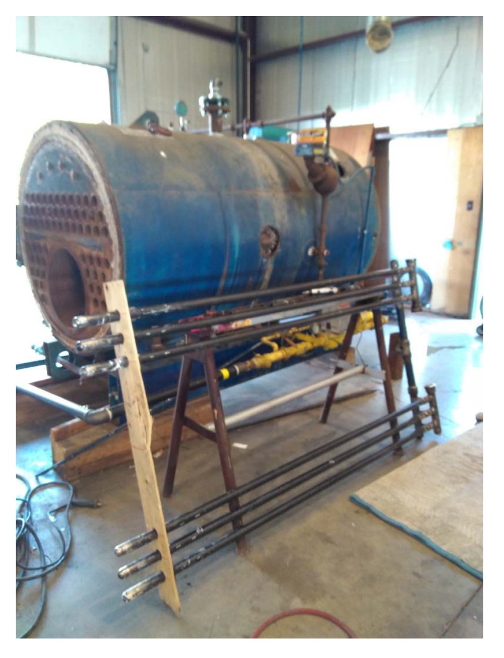
Prototype AA Superheater Installation
C – B 60 BHP Firetube Boiler
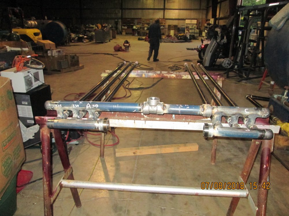
Front side of the 60 BHP superheater assembly showing the saturated steam and superheated steam headers and the 6 superheater elements.
The saturated steam and superheated steam headers are the two horizontal pipes at the front of the photo. The 6 superheater elements are the 6 horizontal tubes that extend toward the rear of the photo.
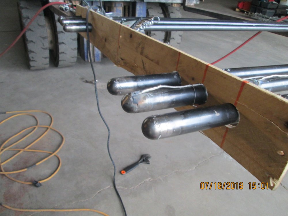
The rear side of the 60 BHP superheater assembly showing the end caps of the 6 superheater elements being held in the assembly fixture. The wire extending from the 2nd superheater element is part of the thermocouple that was installed to obtain test data.
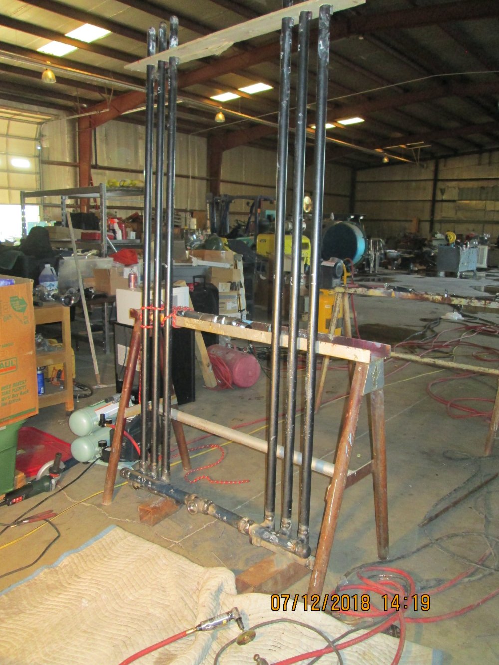
The completed 60 BHP superheater assembly positioned vertically in the assembly fixture.
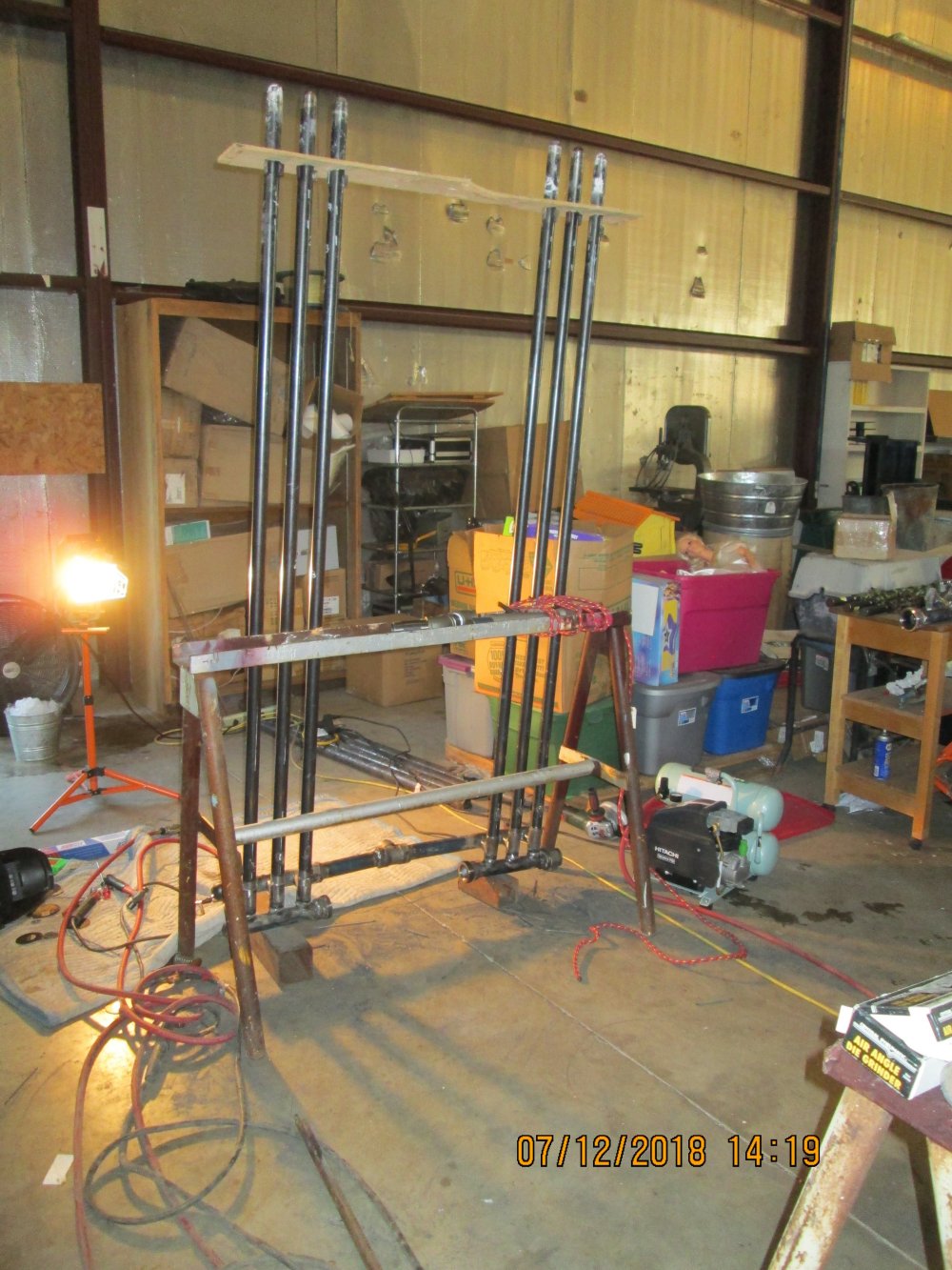
The completed 60 BHP superheater assembly positioned vertically in the assembly fixture.
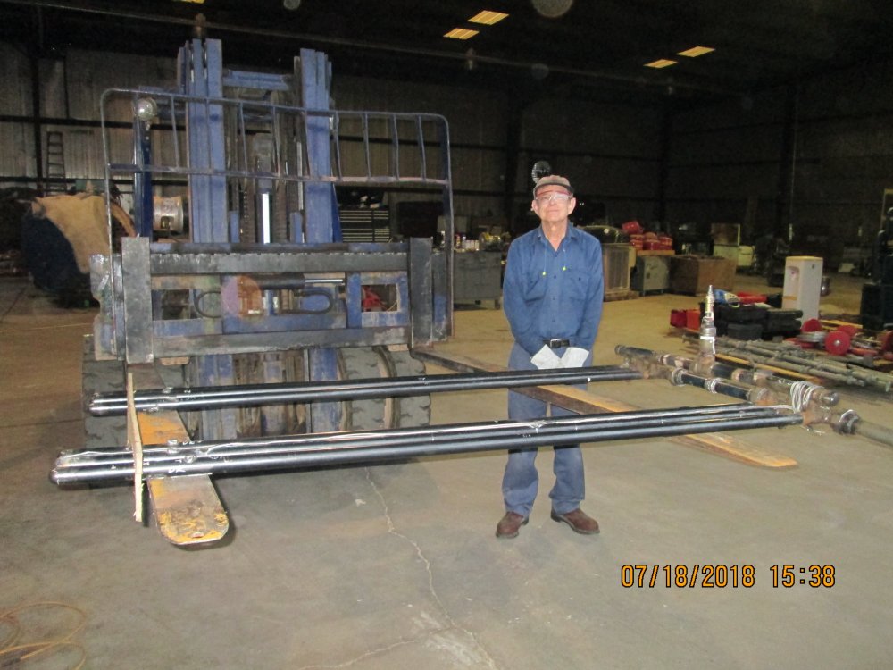
The completed 60 BHP superheater assembly in its normal horizontal position at the start of the installation procedure into the firetube boiler. This is the orientation the superheater assembly will have after it is installed. The worker provides a scale reference of the size of this particular 60 BHP superheater assembly. Superheater elements are 7 feet long.
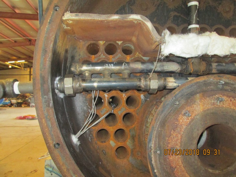
The front side of the 60 HP superheater assembly installed in the firetube boiler at the completion of the installation procedure. The saturated steam and superheated steam headers are the two horizontal pipes. The saturated steam inlet pipe is the vertical pipe at the rear. The superheated steam outlet pipe is the bottom horizontal pipe that exits through the boiler casing wall.
The 6 superheater elements extend through the horizontal boiler tubes and are not visible in this photo.
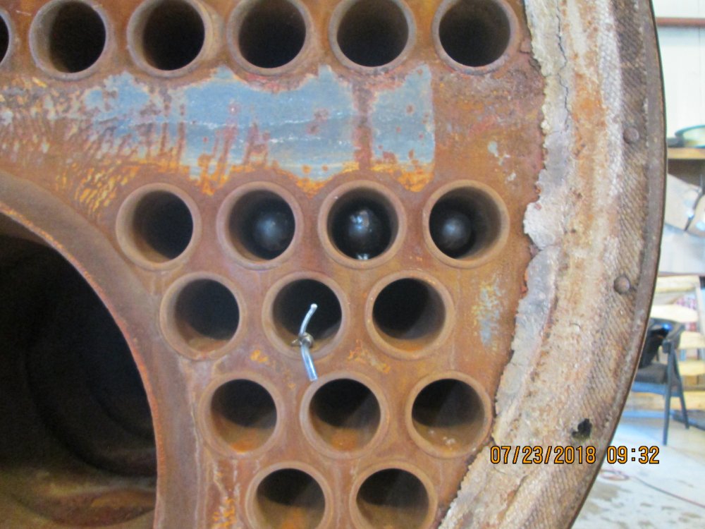
The rear side of the 60 HP superheater assembly at the completion of the installation procedure. Three of the 6 superheater elements and end caps are shown in position within the boiler tubes. The remaining 3 superheater elements are located in the boiler tubes on the opposite side and are not visible in this photo.
